News
A2026-08-07
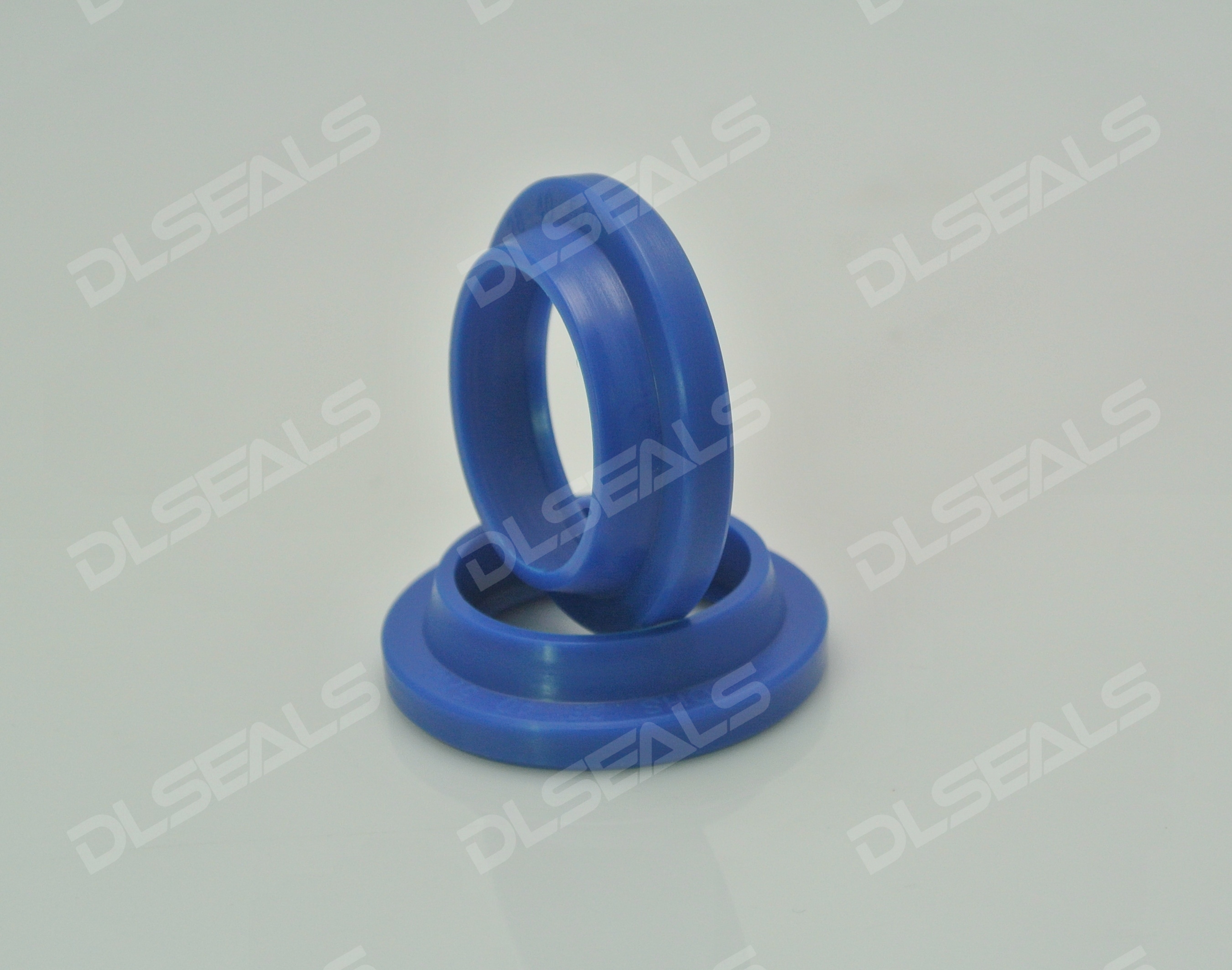
In hydraulic and pneumatic transmission systems, the reciprocating motion of the piston rod inevitably introduces dust, sand, moisture, and particulate matter from the external environment into the cylinder. As the first line of defense for hydraulic and pneumatic cylinders, the DHS double-lip dust seal (commonly known as the DHS wiper ring) is widely used in construction machinery, metallurgical equipment, and general hydraulic systems thanks to its unique double-lip dustproof structure.
DHS dust seals belong to double-acting wiper rings, featuring two functional lips in their cross-sectional design:
Outer Dust Lip (Primary Lip): Located on the side facing the external environment, adhering tightly to the piston rod surface. When the piston rod retracts, the outer lip scrapes off dust, sand, and moisture with an appropriate interference force, effectively preventing external contaminants from entering the cylinder and protecting the main seal and cylinder barrel.
Inner Oil Film Lip (Secondary Lip): Located on the side facing the interior of the cylinder. When the piston rod extends, the trace residual oil film brought out by the main seal is intercepted and scraped back into the cylinder by the inner lip, significantly reducing media leakage and keeping the equipment exterior clean.
Integral Molding Without Metal Skeleton: Molded integrally using high-elasticity polyurethane or rubber materials, offering a compact structure. It requires no metal skeleton support during installation and can be directly flexed and pushed into open or semi-closed grooves, simplifying the assembly process.
The sealing performance and service life of DHS dust seals depend heavily on the choice of substrate material. Below is a performance comparison of commonly used materials for various operating conditions:
| Material Type | Applicable Temperature Range | Wear Resistance / Mechanical Strength | Applicable Media | Typical Application Scenarios |
| Polyurethane (CPU / TPU) (Most Recommended) | -35°C to +100°C | Extremely High (Tear & wear resistance) | Petroleum-based hydraulic oil, lubricating oil | Heavy-duty engineering equipment such as excavators, loaders, and mining machinery |
| Fluororubber (FKM / VITON) | -20°C to +200°C | Moderate | High-temperature hydraulic oil, synthetic oil, chemicals | Metallurgical continuous casters, high-temperature baking equipment, chemical hydraulic systems |
| Nitrile Rubber (NBR) | -30°C to +100°C | Standard | Petroleum-based hydraulic oil, water-glycol | General industrial pneumatic cylinders, light-duty hydraulic equipment, medium/low-pressure systems |
To ensure that the DHS dust seal does not experience lip flipping, extrusion, or dislodgement under extreme operating conditions, groove design and installation must strictly adhere to the following specifications:
Piston Rod and Groove Surface Roughness: The piston rod surface roughness should be controlled at Ra 0.2–0.4 µm. Excessive roughness accelerates lip wear, while excessive smoothness prevents the formation of a microscopic lubricating oil film. The groove surface roughness should be controlled at Ra 1.6–3.2 µm to ensure a firm fit of the seal outer diameter and prevent relative slippage.
Installation Direction and Orientation: Ensure that the larger lip (outer dust lip) faces outward (away from the cylinder) and the smaller lip (inner oil film lip) faces inward (toward the cylinder). Reversing the installation direction destroys dustproofing performance and allows high-pressure oil film to force the seal out of the groove.
Assembly Assistance and Chamfering: A 15°–30° lead-in chamfer must be machined at the end of the piston rod and groove entrance, with all burrs completely removed to avoid scratching the seal lip. Apply a clean layer of hydraulic oil or grease to the piston rod and seal lip before assembly to reduce friction.
Rapid Lip Wear: Usually caused by excessive piston rod surface roughness, highly abrasive ambient dust, or lack of initial lubrication. Upgrading to high-hardness, high-elasticity polyurethane is recommended.
Seal Nibbling or Unilateral Eccentric Wear: Primarily caused by excessive piston rod eccentricity or high lateral loads leading to unilateral overload compression. Installing guide rings (wear rings) to improve alignment is recommended.
Severe Media Leakage: Excessive oil accumulation at the DHS inner lip typically indicates that the primary seal (e.g., Glyd ring, U-cup) is damaged or worn out. The DHS wiper ring cannot withstand system backpressure on its own, requiring prompt inspection or replacement of the primary seal.
In hydraulic system design, reasonable selection of DHS dust seals combined with standardized groove processing significantly extends the service life of primary seals and the entire hydraulic cylinder at a low cost.
[DLSEALS kindly Reminder] Sealing issues? Turn to DLSEALS! As a sealing component manufacturer, we specialize in customizing sealing components, providing a full range of services from design, research and development, production, testing, and more. If you have more information you'd like to know, feel free to contact us directly. DLSEALS's product experts are dedicated to serving you!

GUANGDONG DLSEALS TECHNOLOGY CO.,LTD.
TEL/Whatsapp
:+86 15918359971ADDRESS
:No. 2 Niujiaokeng Road, Baizhoubian, Dongcheng District, Dongguan, Guangdong, China.