News
A2026-05-27
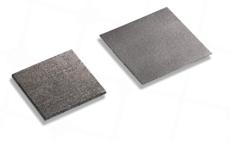
In today's era where modern electronic devices are becoming increasingly high-frequency, highly integrated, and low-profile, Electromagnetic Interference (EMI) and Radio Frequency Interference (RFI) have become invisible, chronic headaches for countless engineers. To ensure that devices remain undamaged in complex electromagnetic environments while simultaneously satisfying strict waterproof and dustproof requirements, an outstanding EMI shielding and sealing material is parameters-critical.
Today, we will dissect a heavy-duty hidden weapon in the electronic shielding industry: the conductive gasket made of Nickel-Graphite in Silicone with a hardness of 60 Shore A.
The robust performance of this conductive gasket stems from its unique composite material formulation. It is essentially an electrically conductive elastomer, created by the flawless fusion of a base matrix and conductive fillers:
Base Matrix: Silicone Rubber
Silicone endows the gasket with superb elastic recovery, excellent high-and-low temperature resistance (typically withstanding -55°C to +160°C), and outstanding weatherability. This ensures the gasket firmly maintains its sealing defense line without suffering from permanent deformation even after long-term compression.
Filler: Nickel-Coated Graphite
This serves as the physical core for both electrical conductivity and shielding. By uniformly coating light non-metallic graphite particles with a layer of high-purity metallic nickel, it retains the exceptional conductive potential of graphite while leveraging nickel to enhance oxidation and corrosion resistance. Compared to expensive pure silver or silver-aluminum fillers, nickel-graphite delivers highly competitive cost-performance advantages while maintaining high shielding effectiveness.
Hardness is a key metric that dictates the practical installation performance of a gasket. 60 Shore A hardness roughly resembles the tactile firmness of a car tire or a hard rubber shoe sole. In conductive gasket applications, this specific hardness offers distinct engineering advantages:
High Structural Strength: Compared to softer conductive rubbers (such as 40 or 50 Shore A), a 60 Shore A gasket is less prone to excessive extrusion deformation or tearing when tightening screws or enduring heavy assembly pressure, thereby maintaining a stable geometric profile.
Reliable Tolerance Accommodation: It is ideally suited for application between high-precision, structurally rigid metal enclosures (such as die-cast aluminum or CNC aluminum alloy chassis), providing continuous rebound contact force to ensure the conductive fillers tightly adhere to the metal substrates.
💡 Engineer's Tip:
Since 60 Shore A is relatively firm, the structural design must guarantee sufficient tightening force (fastener spacing density) to compress the gasket properly to achieve the expected sealing and shielding effects, preventing local chassis warping caused by insufficient enclosure rigidity.
By integrating the flexibility of siloxanes with the conductivity of nickel-graphite, this gasket exhibits a highly balanced, all-around multi-dimensional performance profile:
Excellent Electromagnetic Shielding Effectiveness (SE): Within conventional frequency bands (20MHz - 10GHz), it typically provides a shielding attenuation of 60dB to over 100dB, effortlessly addressing EMI challenges for most commercial, industrial, and even certain military-grade products.
Superb Environmental Sealing (IP Protection): Under proper compression, it can easily achieve IP65 to IP67 ingress protection ratings, effectively blocking the penetration of moisture, salt spray, and dust.
Outstanding Galvanic Compatibility (Anti-Galvanic Corrosion): In humid environments, contact between dissimilar metals triggers galvanic corrosion. When nickel-graphite fillers come into direct contact with commonly used aluminum alloy (such as 6061, ADC12) enclosures, their electrochemical potential difference is minimal. It is far less likely to induce chassis corrosion than traditional silver-based gaskets, significantly enhancing long-term system reliability.
Due to its high reliability and cost-effectiveness, this conductive gasket is extensively utilized across sectors with stringent requirements for interference countermeasures and protection ratings:
| Industry Sector | Typical Application Equipment | Core Functional Role |
| Telecom Base Stations | 5G/6G outdoor enclosures, RRUs (Remote Radio Units), cavity filters | Extreme outdoor weather protection + robust power RF shielding |
| Industrial Control & New Energy | Frequency inverters, photovoltaic inverters, EV powertrain inverters | Blocking high-frequency conduction and radiation interference from high-power switching circuits |
| Smart Security | Outdoor HD PTZ cameras, edge computing gateways | Waterproof & dustproof + ensuring interference-free transmission of HD video signals |
| Medical Electronics | High-frequency electrosurgical units, patient monitors | Preventing cross-interference between medical devices, ensuring precise vital signs data |
The Nickel-Graphite in Silicone 60 Shore A conductive gasket serves as a versatile workhorse and primary defense line in electromagnetic compatibility design. It strikes a sophisticated equilibrium among shielding effectiveness, mechanical hardness, corrosion resistance, and material cost.
When executing structural designs, it is recommended to adhere to the following principles:
Compression Control: The optimal design compression for silicone conductive gaskets is generally between 10% and 25%. Under-compression leads to shielding and sealing failure, while over-compression can induce material fatigue or enclosure deformation.
Groove Design: Given the 60 Shore A hardness, if groove installation is adopted (such as O-ring configurations), ensure to allocate adequate groove width volume (typically the groove width should be 10% to 15% larger than the gasket's wire diameter). This is because rubber is virtually incompressible in volume when compressed and can only expand laterally.
[DLSEALS kindly Reminder] Sealing issues? Turn to DLSEALS! As a sealing component manufacturer, we specialize in customizing sealing components, providing a full range of services from design, research and development, production, testing, and more. If you have more information you'd like to know, feel free to contact us directly. DLSEALS's product experts are dedicated to serving you!

GUANGDONG DLSEALS TECHNOLOGY CO.,LTD.
TEL/Whatsapp
:+86 15918359971ADDRESS
:No. 2 Niujiaokeng Road, Baizhoubian, Dongcheng District, Dongguan, Guangdong, China.